As mentioned above, stabilization mode of power
supply is roughly classified into switching mode and series mode.
Nowadays, power supply means switching system in many cases due
to high efficiency and compact. Here, the mechanism of switching
power supply is explained.
<< Operation principle >>
Basic circuit and components of switching power supply is shown
in Figure 1.5.
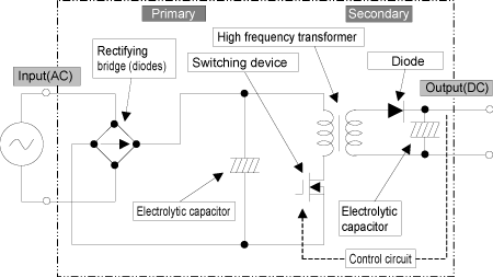
Figure 1.5 Basic circuit and components of
switching power supply
- Rectifying bridge: To rectify AC current to one direction
- Electrolytic capacitor: To build up electricity and work to keep
voltage
- High frequency transformer: To transfer energy from primary to
secondary
- Control circuit: To control ON/OFF timing of switching device
to stabilize secondary voltage
In this system, input (alternate current: AC) is converted to output
(direct current: DC). Input side is called "Primary output
side is called "Secondary" to which energy is transferred
via high frequency transformer.
Now, referring to the diagram above, operation mechanism of switching
power supply can be explained as follows,
(1) Connect alternate current (AC) to switching power supply.
(2) The AC is rectified by rectifying bridge and smoothed by primary
electrolytic capacitor after that.
(3) Switching operation (repeated electric ON/OF operation) of switching
device generates alternate current with high frequency.
(4) Energy (AC) is transferred via high frequency transformer to
secondary side.
(5) Rectified by secondary diode and smoothed by secondary electrolytic
capacitor, the energy is converted to DC (direct current) as output.
(6) To keep output voltage stabilized, switching is controlled through
feedback system.
That is the basic operation principle of switching power supply.
<< Circuit method >>
Circuit method in switching power supply depends on "DC-DC
converter's mode which converts DC to AC with high frequency, and
again convert it back to DC." Also, in determining switching
cycle of DC-DC converter, it is classified into two modes. One is
called self-excitation mode whose switching block determines the
switching cycle on its own. The other is called separate excitation
mode (PWM mode) that has an oscillator to decide the frequency independently.
Self-excitation mode's features are "Cost is low due to simple
circuit structure," and "the frequency changes according
to input voltage and load condition." Separate excitation mode's
features are "Cost is generally high compared to self-excitation
mode as it uses ICs," and "the frequency is constant."
Also, there are another two modes when energy is transferred from
primary to secondary. One is called forward mode where the energy
is transferred during ON period, and the other is called flyback
mode where the energy is transferred during OFF period.
(1) Single forward
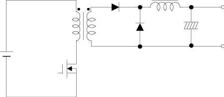
Figure 1.6 Single forward
This mode is used in many switching power supplies due to simple
structure and stable control. (Adopted in our Nonstop power supplies
in many cases). Separate excitation mode is mostly used from small
power to high power as well. Disadvantage is poor usability of transformer.
(2) Flyback (called RCC)
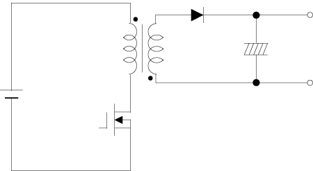
Figure 1.7 Flyback
This mode need a few components and is the simplest mode, but not
suitable to high power. This is mostly adopted to small power, but
input voltage range is wide.
(3) Push-pull
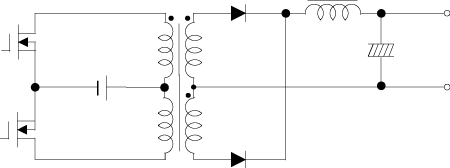
Figure 1.8 Push-pull
This mode uses two switching devices and coils to turn on alternately.
Bias magnetism of transformer is critical.
(4) Half-bridge
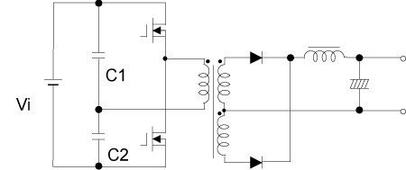
Figure 1.9 Half-bridge
Operation is the same as push-pull mode, but as the applied to
transform is half of Vi, low voltage transistors can be used. The
usability of transformer is better, but the temperature rise of
each capacitor caused by switching current that flows in capacitors
is critical.
(5) Full-bridge
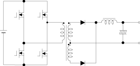
Figure 1.10 Full-bridge
Circuit structure is complicated, but low voltage switching devices
can be used. It gives high efficiency and is adopted to high power.
Usability of transformer is the highest of all. Critical points
are bias magnetism and penetration current between upper and lower
devices (FETs).
(6) MagAmp (Magnetic amplifier)

Figure 1.11 Magnetic amplifier
This mode is to control phase in pulse utilizing magnetic saturation
of amorphous core which has rectangular hysteresis property to stabilize
output voltage.
(7) Step-down chopper

Figure 1.12 Step-down chopper
This mode is non-insulated type to convert to low voltage without
transformer.
(8) Step-up chopper (also called flyback)

Figure 1.13 Step-up chopper
This mode is non-insulated type to convert to high voltage without
transformer.
|


